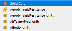
Now select all points on the grid by using the Select Points on (d) function in the upper panel of the render view and click Copy Active Selection in the Properties Panel. Just right-click on ProgrammableFilter in the pipeline browser, then Add Filter->ExtractSelection.

The output should look as in Figure 3.Įxtract grid points: To solve the problem with the shifted cells, we now take the ProgrammableFilter, extract all points out of it and add new cells based on the extracted points. Important: In python3, the function xrange was renamed to range. Y = np.empty(len(longitude), dtype=np.float64) X = np.empty(len(longitude), dtype=np.float64) # define coordinate transform function by defining the coordinates In the added filter set Output Data Set Type to Same as Input add the following script: from pyproj import Transformer, transform No right–click on swc.nc in the pipeline browser and then Add Filter -> Alphabetical -> ProgrammableFilter. Just open a python shell in ParaView and add the directory were you installed pyproj to the system path: ('path/to/pyproj') After installing pyproj you gotta tell ParaView were this library is located.
#Paraview netcdf install
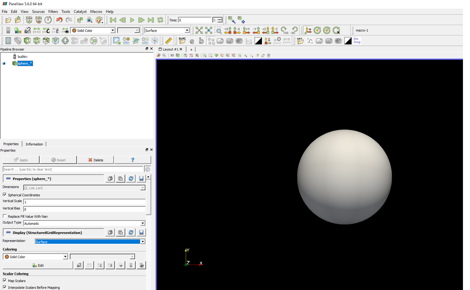
If you do not have any C compiler installed, which can be the case on Windows, then download the corresponding precompiled python wheel file (cpXX in the filename reflects the python version) and install via pip install pyproj‑2.2.2‑cp38‑cp38‑win_amd64.whl (example). Make shure that you have the same python version as used by ParaView. In case you have a C compiler installed you can install pyproj using pip via pip install pyproj. You have to install it into your local python folder as there is no option to install in the python version that comes with ParaView-let’s say it did not find any. Within the python script we use the library pyproj for the cordinate transformation. Therfore we will use a ProgrammableFilter to include a python script. Gauss–Kruger–4 is a cartesisn coordinate system that uses m as units. Before we need to transfrom the longitude–latitude coordinates.Īfterwards, you have to transform the coordiante system from longitude–latitude (EPSG:4326) to Gauss–Kruger (EPSG:5684), which is used by this ogs_mesh.vtu. The cells are now shifted in x and y direction, so we need another trick later on. Unfortunately, the cell centered points of the original NetCDF file are now vertices of quadriliteral cells in thevtkStructuredGrid`. It’s output type should be vtkStructuredGrid'. Your imported data should look like in Figure 2, containing longitude and latitude as coordinates. Sometimes it may be necessary to first check Spherical coordinates, click apply, then uncheck Spherical coordinatesand click Apply again. Just uncheck Spherical coordinates to read in the coordinates as cartesian click Apply. mHM NetCDF files do have unregular cell coordinates, which is not ideal for ParaView to import. swc.nc will show up in the pipeline browser. As swc.nc uses the CF conventions, choose NetCDF Reader.

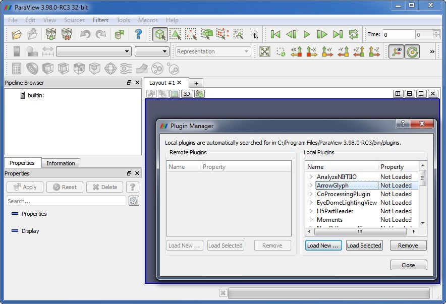
A prompt will asks you to specify a NetCDF reader as there are different NetCDF formats out there.

soil water content) linked to the raster cell.įor time-dependent data, usually one array per time step is defined.Ĭlick File->Open select swc.nc. Each raster/array cell is defined by coordinates of the cell center and variables (e.g. This means that a raster (unifrom grid) is defined as an array. Usually NetCDF is a raster based–file format.


 0 kommentar(er)
